
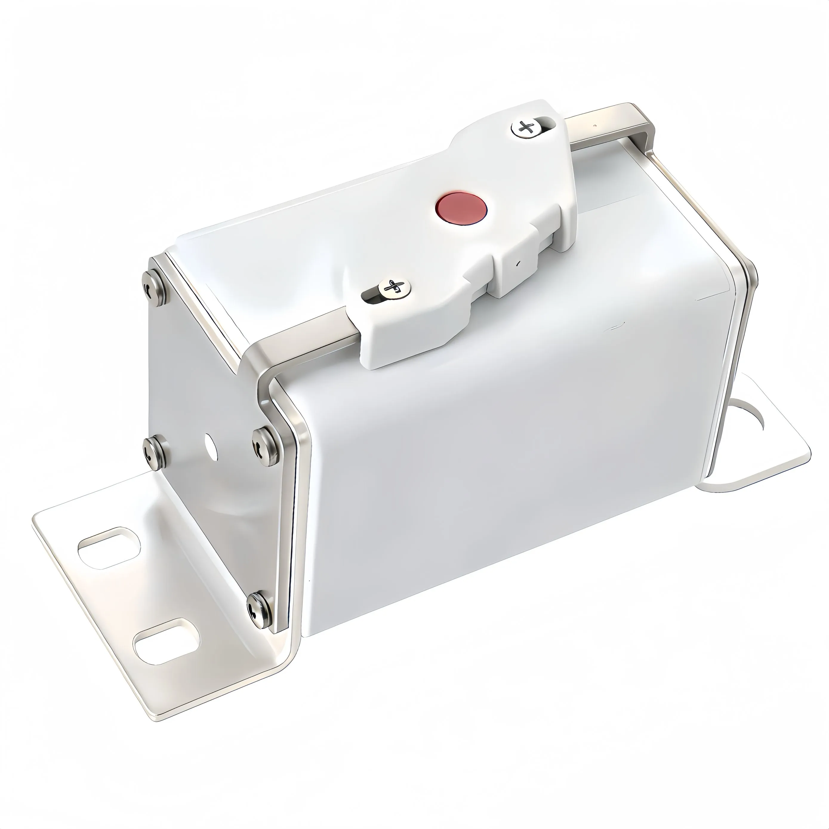
Sizing an energy storage fuse for a 1500 V battery rack looks like a five-minute job until you read the fault current. A lithium rack does not ramp up to its short-circuit value the way a generator does — the current is available the instant a contactor welds or a cable gets crushed during service. We have reviewed rack designs where the nominal string current was 125 A and the prospective fault current at the same terminals was more than twenty times that. If the protective device was chosen by matching the nominal current alone, it simply was not a protection device. It was a piece of metal in a holder. This guide walks through the sizing sequence we actually use when a customer sends us a rack specification. It is written for engineers and procurement teams who need to make a defensible choice, not for someone looking for a part number.
Why 1500 V Changes the Rules
Moving from 1000 V to 1500 V DC is the industry's answer to a simple economic problem: higher voltage means lower current for the same power, which means thinner cables, smaller busbars, and fewer parallel strings. It also makes the protection problem harder. Direct current has no natural zero crossing. When an AC fuse interrupts a fault, the current passes through zero twice per cycle and the arc gets a free chance to extinguish. A DC arc has to be forced out — stretched, cooled, and split inside the fuse body until the voltage across the arc exceeds the system voltage driving it. The higher the system voltage, the more arc energy has to be absorbed before the circuit is safe. That is why a device rated for 1000 V DC is not a 1500 V device with margin. The 1500 V rating is a statement about arc-quenching capability, creepage distance, and the mechanical design of the body, not just a number printed on a label. There is a second consequence. At 1500 V, the same insulation defect that would have been a nuisance at 400 V becomes a tracking and fire risk. Standards bodies know this, which is why creepage and clearance requirements at these voltages drive the physical size of holders and fuse bases in ways that surprise people who have only worked on low-voltage panels.
Start From Prospective Short-Circuit Current, Not Nominal Current
The first number you need is not the operating current. It is the prospective short-circuit current at the point where the fuse will sit. For a battery rack this is governed largely by the internal resistance of the cell string plus the resistance of the busbars, connectors, and cabling back to the fault. Lithium cells — particularly LFP — have very low internal impedance, which is exactly what makes them excellent at delivering power and dangerous during a fault. In practice, the racks we are asked to protect land somewhere between 10 kA and 30 kA of prospective fault current. You should not guess. Either measure it, model it from cell impedance data supplied by the cell manufacturer, or ask your rack integrator for a fault study. If nobody can produce one, that is a red flag about the whole design, not just the fuse. You also need the time constant of the fault loop, usually expressed as L/R. Battery circuits are inductive relative to their resistance, and time constants of a few milliseconds are common. This matters because DC breaking capacity is specified at a test time constant. If your real loop is slower than the test condition, the effective breaking capability of the device drops.
Apply Derating Before You Fall in Love With a Rating
A fuse rated at 200 A is not a fuse that will happily carry 200 A forever inside a sealed battery container in summer. Several factors push the usable continuous current below the nameplate value:
- Ambient temperature inside a container can reach 45 °C to 55 °C at the rack, and higher near the top of the enclosure
- Cyclic loading — charge in the morning, discharge in the evening — produces repeated thermal expansion and contraction, which fatigues the element over years
- Sealed enclosures with limited convection keep heat in rather than moving it out
- Altitude reduces convective cooling for air-cooled installations
- Multiple fuses mounted side by side in a busbar assembly heat each other
Manufacturers publish derating curves for exactly this reason. As a working rule, we ask customers to keep continuous rack current at roughly 70 % to 80 % of the fuse rating for a typical container environment, then confirm against the actual derating curve for the specific product. If the curve says something different, the curve wins. Under-sizing here is what produces the classic field complaint: a fuse that runs hot, discolours its end caps, and eventually opens with no fault at all. That is not a defective fuse. It is a fuse that was asked to carry more than it was derated to carry.
Check Breaking Capacity Against the Worst Case
Breaking capacity is the maximum fault current the device can interrupt safely at its rated voltage. Two rules apply. First, the rating must exceed the prospective fault current at the installation point, with margin. Do not select a device that sits right at the calculated value. Fault current estimates carry uncertainty, battery racks get expanded, and additional strings get paralleled later. Second, and more often missed, the voltage rating and the time constant must both be appropriate. A DC rating obtained at a short time constant does not automatically transfer to a slower loop. Read the datasheet carefully: if the manufacturer publishes breaking capacity against a table of time constants, use the row that matches your system. This is also where we see confusion between product families. A general-purpose industrial fuse, a semiconductor protection fuse, and a dedicated energy storage fuse are tested and characterised differently. They are not interchangeable because the current and voltage numbers look similar on a comparison sheet.
Coordinate the Curve With the Contactor and the BMS
Protection in a BESS is a team sport. The contactor handles routine switching and, in many designs, is expected to clear moderate overloads. The BMS monitors cell voltages and temperatures and can command a shutdown. The fuse is the last line: it deals with the fault that the other two cannot. For that division of labour to work, the time-current curve of the fuse needs to sit above the operating envelope of the contactor across the overload region, and cross into fast operation only in the short-circuit region. If the two curves overlap badly, you get one of two failures. Either the fuse clears a transient that the contactor should have handled, and the truck rolls for a fuse change, or the contactor tries to interrupt current beyond its capability and welds. Pre-charge inrush is the other coordination trap. When a rack is connected to an already-energised DC bus, the inrush can be several times nominal for tens of milliseconds. The fuse has to survive that without cumulative damage, otherwise you will see fuses that open during commissioning on a healthy system.
Verify Let-Through Energy Against What You Are Protecting
Interrupting the fault is only half the job. The other half is limiting the energy that gets through before the fuse clears. Two quantities matter: peak let-through current, and let-through I2t, expressed in ampere-squared seconds. Your busbars, connectors, cell terminals, and any semiconductors in the loop all have a withstand limit. The protective device's let-through I2t must be below the weakest of those limits, with margin. This is why fast-acting devices with strong current-limiting behaviour are preferred in battery circuits. Clearing in a fraction of a millisecond rather than several milliseconds is not a marketing difference; it is the difference between a busbar that survives and a busbar that deforms.
A Sizing Sequence You Can Copy
When a rack specification lands in our inbox, we work through it in this order: 1. Establish the maximum continuous current and the duty cycle of the rack 2. Obtain the prospective short-circuit current and the loop time constant at the fuse location 3. Apply environmental derating to get the minimum acceptable continuous rating 4. Select a voltage rating that meets or exceeds the maximum system voltage, including any transient overshoot 5. Confirm breaking capacity at both the calculated fault current and the real time constant 6. Plot the time-current curve against contactor capability, BMS thresholds, and pre-charge inrush 7. Check let-through I2t and peak current against the withstand of every component in the fault path 8. Document the selection with the assumptions, so the next engineer can audit it Skipping step 2 or step 7 is how expensive mistakes get made.
Summary
Choosing an energy storage fuse for a 1500 V rack is a sequence, not a lookup. Fault current sets the breaking requirement, environment sets the continuous requirement, coordination sets the curve shape, and let-through energy sets how much of the rack survives the event that the fuse was fitted for. Work through those four in order and the selection defends itself in any design review.
About Our Energy Storage Protection Range
GFEFUSE is the brand of Dongguan Gongfu Electronics Co., Ltd., an electronic protection device manufacturer founded in Dongguan, Guangdong in 2013. We develop, produce, and sell fuses, fuse holders, fuse boxes, and the peripheral accessories that go with them, with five advanced production lines and a thirteen-person R&D team supporting custom work. For battery energy storage specifically, our energy storage fuse range covers high-voltage DC protection for containerised and cabinet systems, and it sits alongside our square high speed fuse series for semiconductor and converter protection within the same cabinet. Where a rack design calls for bolted connections rather than clip mounting, the bolt down fuse options in our catalogue are the usual answer, and our wider high voltage fuse portfolio covers the rest of the DC distribution chain. Our products carry UL, cULus, TUV, CE, and CQC certification and comply with RoHS and REACH directives. They are used in consumer electronics, automotive electronics, power equipment, communication systems, and new energy applications, and they are exported to customers overseas.
Conclusion
A 1500 V BESS rack concentrates an enormous amount of energy behind a very low impedance. The fuse in that circuit is the only device that will act without software, without a control signal, and without a power supply. Sizing it from fault current rather than from nominal current, derating it for the environment it actually lives in, and checking the let-through energy against the weakest component in the loop turns it from a part number into engineered protection.
Tell us your rack voltage, continuous current, prospective fault current, and loop time constant. Our engineering team will run the sizing sequence and send back a recommendation you can put straight into your design review.
Frequently Asked Questions
Answers to the questions we get most often when a customer is sizing protection for a battery rack.
How do I size an energy storage fuse for a 1500 V BESS rack?
Start with the prospective short-circuit current and loop time constant at the fuse location, not the nominal rack current. Apply environmental derating to find the minimum continuous rating, then confirm the voltage rating, breaking capacity, and let-through I2t. Finally check the time-current curve against contactor capability and pre-charge inrush.
Can I use a 1000 V DC energy storage fuse in a 1500 V system?
No. DC arc interruption depends on voltage, and a 1000 V rating means the device was tested and characterised for 1000 V. At 1500 V the arc may not be extinguished, and creepage distances may also be insufficient. Always select a device rated at or above the maximum system voltage including transients.
What breaking capacity does an energy storage fuse need?
It must exceed the prospective short-circuit current at the installation point with margin, and it must be valid at the actual time constant of your fault loop. Typical containerised racks fall in the 10 kA to 30 kA range, but you should confirm with a fault study rather than assume.
Why does my energy storage fuse run hot at rated current?
The usual cause is missing environmental derating. High ambient temperature inside the enclosure, cyclic loading, and poor convection all reduce the current the device can carry continuously. Check the manufacturer's derating curve and confirm the actual terminal temperature under load.
How often should an energy storage fuse be replaced?
A fuse that has not operated does not have a fixed replacement interval, but it should be included in periodic inspection. Look for discolouration, loose terminals, and elevated temperature under load. Any fuse that has cleared a fault should be replaced, and the cause of the fault investigated before re-energising.